#converter

icon subthematics
Let s Explore India (Most Famous Attractions in India)
Category

Ebooks

Let's Explore India (Most Famous Attractions in India)

Baby Professor

Let s Explore India (Most Famous Attractions in India) Alternate Text
Category

Ebooks

Jeunesse

Let's Explore India (Most Famous Attractions in India)

Baby Professor

Book

32 pages

Flag

English

Let s Explore Italy (Most Famous Attractions in Italy)
Category

Ebooks

Let's Explore Italy (Most Famous Attractions in Italy)

Baby Professor

Let s Explore Italy (Most Famous Attractions in Italy) Alternate Text
Category

Ebooks

Voyages - guides

Let's Explore Italy (Most Famous Attractions in Italy)

Baby Professor

Book

32 pages

Flag

English

Let s Explore Japan (Most Famous Attractions in Japan)
Category

Ebooks

Let's Explore Japan (Most Famous Attractions in Japan)

Baby Professor

Let s Explore Japan (Most Famous Attractions in Japan) Alternate Text
Category

Ebooks

Voyages - guides

Let's Explore Japan (Most Famous Attractions in Japan)

Baby Professor

Book

32 pages

Flag

English

Cocoa Application Tutorial
Category

Documents

Cocoa Application Tutorial

Jennifer Aubinais

Cocoa Application Tutorial Alternate Text
Category

Documents

Savoirs

Cocoa Application Tutorial

Jennifer Aubinais

Book

41 pages

Flag

English

Creating a GUI with JFC/Swing
Category

Documents

Creating a GUI with JFC/Swing

Creating a GUI with JFC/Swing Alternate Text
Category

Documents

Savoirs

Creating a GUI with JFC/Swing

Book

1273 pages

Flag

English

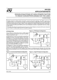
INTRODUCTION Three different configurations that an L6561 based flyback converter can assume have been identified They are illustrated in fig Configurations a and b are basically conventional flyback converters The former works in TM Transi tion Mode i e on the boundarybetween continuous and discontinuous inductor current mode therefore at a frequency depending on both input voltage and output current The latter works at a fixed frequency imposed by the synchronisation signal and is there fore completely equivalent to a flyback converter based on a standard PWM controller Configuration c which most exploits the aptitude of the L6561 for performing power factor correction works in TM too but quite differently: the input ca pacitance is so small that the input voltage is very close to a rectified sinusoid Besides the control loop has a narrow bandwidth so as to be little sensitive to the twice mains frequency ripple appearing at the output
Category

Documents

INTRODUCTION Three different configurations that an L6561 based flyback converter can assume have been identified They are illustrated in fig Configurations a and b are basically conventional flyback converters The former works in TM Transi tion Mode i e on the boundarybetween continuous and discontinuous inductor current mode therefore at a frequency depending on both input voltage and output current The latter works at a fixed frequency imposed by the synchronisation signal and is there fore completely equivalent to a flyback converter based on a standard PWM controller Configuration c which most exploits the aptitude of the L6561 for performing power factor correction works in TM too but quite differently: the input ca pacitance is so small that the input voltage is very close to a rectified sinusoid Besides the control loop has a narrow bandwidth so as to be little sensitive to the twice mains frequency ripple appearing at the output

Claudio Adragna

INTRODUCTION Three different configurations that an L6561 based flyback converter can assume have been identified They are illustrated in fig Configurations a and b are basically conventional flyback converters The former works in TM Transi tion Mode i e on the boundarybetween continuous and discontinuous inductor current mode therefore at a frequency depending on both input voltage and output current The latter works at a fixed frequency imposed by the synchronisation signal and is there fore completely equivalent to a flyback converter based on a standard PWM controller Configuration c which most exploits the aptitude of the L6561 for performing power factor correction works in TM too but quite differently: the input ca pacitance is so small that the input voltage is very close to a rectified sinusoid Besides the control loop has a narrow bandwidth so as to be little sensitive to the twice mains frequency ripple appearing at the output Alternate Text
Category

Documents

Corrigés de devoir

INTRODUCTION Three different configurations that an L6561 based flyback converter can assume have been identified They are illustrated in fig Configurations a and b are basically conventional flyback converters The former works in TM Transi tion Mode i e on the boundarybetween continuous and discontinuous inductor current mode therefore at a frequency depending on both input voltage and output current The latter works at a fixed frequency imposed by the synchronisation signal and is there fore completely equivalent to a flyback converter based on a standard PWM controller Configuration c which most exploits the aptitude of the L6561 for performing power factor correction works in TM too but quite differently: the input ca pacitance is so small that the input voltage is very close to a rectified sinusoid Besides the control loop has a narrow bandwidth so as to be little sensitive to the twice mains frequency ripple appearing at the output

Claudio Adragna

Book

20 pages

Flag

English

J2EE Tutorial
Category

Documents

J2EE Tutorial

J2EE Tutorial Alternate Text
Category

Documents

Savoirs

J2EE Tutorial

Book

517 pages

Flag

English

  • 1
Alternate Text